
Views: 0 Author: Site Editor Publish Time: 2026-08-02 Origin: Site


Investing in high-resolution cameras or CMOS TDI sensors often yields diminishing returns if the optical front-end introduces edge distortion. Lenses must resolve fine defects reliably at extreme production speeds. Otherwise, you severely compromise the potential of your premium sensors. Specialized optics play a critical role in continuous roll-to-roll and flat-surface inspection. Continuous motion and exceptionally wide fields of view rapidly expose the physical limitations of standard machine vision lenses. Area scan optics struggle to maintain edge-to-edge sharpness across wide substrates.
Upgrading to a purpose-built Line Scan Lens directly translates to higher defect catch rates. It significantly reduces false rejects and ensures scalable quality control for demanding wide-web manufacturing. In this guide, you will learn how optical architecture impacts system performance. We will also reveal practical steps to specify the perfect lens for your exact line speed and sensor format.
Off-the-shelf area scan lenses struggle immensely under continuous, high-speed motion. Manufacturers often deploy them on wide substrates like paper, film, battery foil, or semiconductor glass. However, these standard optics produce severe motion blur. They also compromise edge-to-edge sharpness. The outer edges of the field view suffer from severe optical roll-off. You lose critical pixel data where you need it most.
Optical distortion creates a massive operational burden. Poor image quality forces engineers to rely on software-heavy image correction. Algorithms must stretch and warp the captured image to compensate for the physical lens flaws. This intensive processing causes several critical failures:
Software cannot magically replace missing optical data. Relying on algorithms instead of quality optics creates an unstable inspection environment. A successful optical integration completely avoids these pitfalls. It guarantees 100 percent surface coverage across the entire material width. You experience zero image stitching artifacts. The system reliably detects micron-level defects at maximum web speeds. These defects include micro-scratches, pinholes, and microscopic coating voids. Achieving this benchmark requires precision glass engineered specifically for continuous motion.
Engineers must understand the fundamental optical design logic differentiating these two technologies. Solution categories divide into two distinct architectures. Area scan lenses optimize light gathering for a rectangular 2D grid. Their resolution performance drops sharply toward the edges. Conversely, line scan optics perfectly resolve a single 1D line. They maintain this extreme resolution across a massive image circle.
This architecture provides a clear roll-to-roll advantage. The line scan approach offers the only truly scalable method for continuous webs. Think about inspecting a two-meter-wide sheet of copper foil. Using area scan cameras requires a multi-camera array. You must overlap their fields of view. You also need complex strobe lighting synchronization. Furthermore, the software must stitch these overlapping images together in real-time. Line scan eliminates this nightmare. A single robust camera and lens combination captures the entire web width continuously.
High-speed web inspection heavily relies on CMOS TDI (Time Delay Integration) sensors. TDI synergy requires specialized optics to function properly. You must maximize light throughput to keep exposure times microscopic. Simultaneously, the lens must prevent chromatic aberration. Chromatic shifts blur the sequential lines during the TDI integration process. A standard lens will scramble this delicate color alignment. Precision optics ensure the delayed integration aligns perfectly row after row.
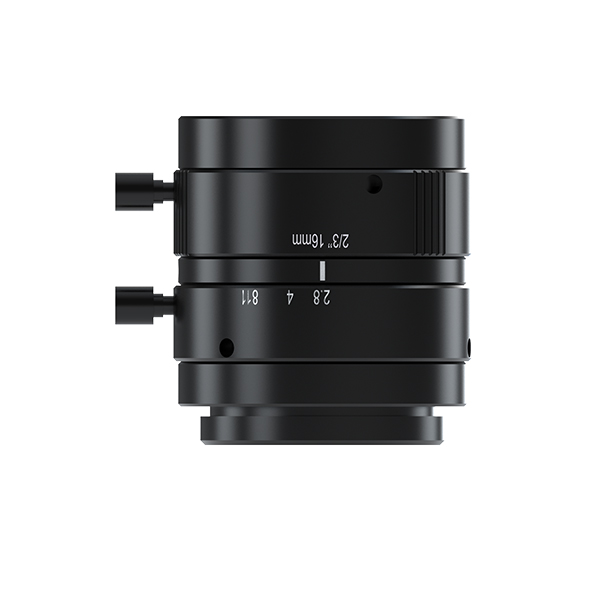
You must evaluate specific physical metrics when selecting a Surface Defect Detection Lens. Never rely on marketing specifications alone. Look at the actual engineering data corresponding to your environment.
First, analyze the Modulation Transfer Function (MTF). Guide your evaluation based on your specific defect size requirements. Do not just look at theoretical maximums at infinity focus. Check the MTF charts for your exact working distance. Verify the contrast ratios at the spatial frequencies matching your sensor pixel size. If your sensor uses 5µm pixels, the lens must deliver high contrast at 100 line pairs per millimeter.
Next, establish a strict distortion benchmark. A high-performance industrial lens must deliver exceptionally low optical distortion. We typically target distortion levels below 0.1 percent. This tight tolerance prevents pixel mapping errors. It ensures your software analysis remains mathematically accurate across the entire web.
You must also match the magnification and image circle. High-resolution line scan sensors use massive arrays. Formats like 8k, 12k, or 16k require lenses possessing huge image circles. If the lens image circle falls short, you will experience severe vignetting. The edges of your image will turn completely dark, hiding critical edge defects.
Finally, consider the illumination integration. Wide-web inspection depends on high-intensity line lighting. Typical setups use coaxial or darkfield geometries. The lens coating must explicitly minimize internal reflections. Poorly coated lenses create ghosting artifacts. These artifacts blind the sensor to subtle surface variations.
Optical Specifications Evaluation Matrix
| Evaluation Metric | Standard Area Lens | Optimized Line Scan Lens |
|---|---|---|
| MTF Optimization | Infinity focus, center-weighted | Specific macro working distances, uniform edge-to-edge |
| Distortion Level | 1.0% to 3.0% (Barrel/Pincushion) | < 0.1% (Near zero mapping errors) |
| Image Circle Size | 11mm to 23mm (Standard formats) | 60mm to 90mm+ (Large format arrays) |
| Vignetting Control | High risk on wide sensors | Zero roll-off across the entire array length |
The factory floor introduces severe mechanical challenges. Heavy machinery generates constant vibration. This implementation risk routinely destroys optical alignment. High-performance optics require robust, industrial-grade mechanical mounts. Standard C-mounts cannot support the weight of large format lenses. They also lack the necessary thread engagement to prevent micro-movements. You should specify M72 or M90 threaded mounts. These massive mechanical interfaces lock the optical axis rigidly in place.
Web flutter presents another massive challenge. Continuous substrates rarely lay perfectly flat. They ripple and bounce along the Z-axis as tension changes. You must carefully balance the lens aperture. Adjusting the f-stop increases your depth of field. However, stopping down the aperture starves the sensor of light. You must calculate the exact sweet spot. The lens must capture sharp images despite web flutter while maintaining adequate exposure at high speeds.
Alignment complexity demands absolute precision. Installation requires perfect pitch, roll, and yaw positioning. A fraction of a degree off-axis ruins your spatial resolution. The focal plane must perfectly intersect the moving web across its entire width. We highly recommend using micrometer-adjusted staging. This hardware allows you to dial in the optical alignment mechanically before applying any software adjustments.
Specify the right lens by following a systematic approach. Guesswork leads to costly downtime and false rejects. Use this practical four-step logic to guarantee compatibility and performance.
The lens acts as the primary bottleneck for data quality in continuous inspection systems. Software algorithms simply cannot recover lost optical data. If the glass fails to resolve a micron-level pinhole, the entire inspection system fails. Choosing a purpose-built lens ensures high-fidelity image capture. It secures scalable, high-speed performance across your entire production line.
Engineers must move away from basic datasheet comparisons. Request a proof-of-concept optical test from your vendor. Alternatively, commission a detailed feasibility study. Always use your specific substrate samples during these evaluations. Verify the optical performance physically on a test bench before committing to a final machine design.
A: The primary difference lies in the image circle size and focal optimization. Area scan lenses project light onto a small rectangular 2D grid. They often lose sharpness at the edges. Conversely, line scan optics capture a single 1D continuous line. They project an exceptionally large image circle to cover massive sensor arrays uniformly without vignetting.
A: Web flutter shifts the material along the Z-axis, moving it out of optimal focus. This requires a lens configured for an adequate depth of field. You must carefully balance the aperture size. A smaller aperture improves focus depth but limits light gathering, which is problematic in fast-moving environments.
A: Yes. TDI sensors rely on sequential delayed imaging across multiple pixel rows. This architecture requires incredibly high light transmission. Furthermore, the lens must feature strict color correction to eliminate chromatic aberration. Low chromatic aberration ensures the delayed integration aligns perfectly without color blurring.
A: You prevent vignetting by carefully matching the lens specifications to your camera hardware. Select a lens featuring an image circle that strictly exceeds the physical length of your line scan sensor array. Proper coaxial or uniform line illumination also prevents edge darkening.


