
Views: 0 Author: Site Editor Publish Time: 2026-08-03 Origin: Site


Standard area scan imaging often struggles with motion blur, excessive image stitching, and physical space limits in high-speed manufacturing environments. These optical bottlenecks create significant operational friction when production line speeds increase. A Line Scan Imaging Lens captures a single, continuous row of pixels, bypassing these limits entirely. It builds a seamless 2D image line by line as the target object or the camera moves. Transitioning to this specialized architecture requires careful optical evaluations to guarantee long-term success. You need precise matching between the chosen lens, the linear camera sensor, and the illumination source. In this guide, we will explore core applications, implementation risks, and exact specifications needed to deploy this technology. You will learn how to bypass standard inspection limits and build a highly reliable automated vision system.
Standard area scan cameras fail dramatically under specific manufacturing extremes. Inspecting continuous rolls of material demands a fundamentally different approach. Area sensors capture discrete, rectangular frames continuously. If the target material moves too fast, you inevitably get motion blur. You also face complex software stitching to merge these overlapping frames. This software stitching introduces heavy processing overhead. We often see standard imaging setups choke during high-speed sorting tasks. The system simply drops frames when data bandwidth saturates.
Success in continuous manufacturing relies on very strict operational criteria. First, you need 100 percent surface inspection. Blind spots are completely unacceptable. Overlapping frames often create duplicate defect reports. Second, you must reduce false rejects on the production line. Standard lenses often suffer from optical distortion near the outer edges. This edge distortion triggers false alarms in your quality control software. A continuous line setup solves this problem neatly. It utilizes only the optical center of the lens continuously.
Consider the hardware outcome of this transition. High-speed systems require highly precise synchronization hardware. However, they drastically reduce total equipment counts in large-format inspections. You can replace an array of multiple area scan cameras with just one single unit. This consolidation simplifies networking cables and trigger mechanisms. It streamlines the physical footprint over the conveyor. You eliminate the complex calibration matrix needed to align multiple 2D cameras.
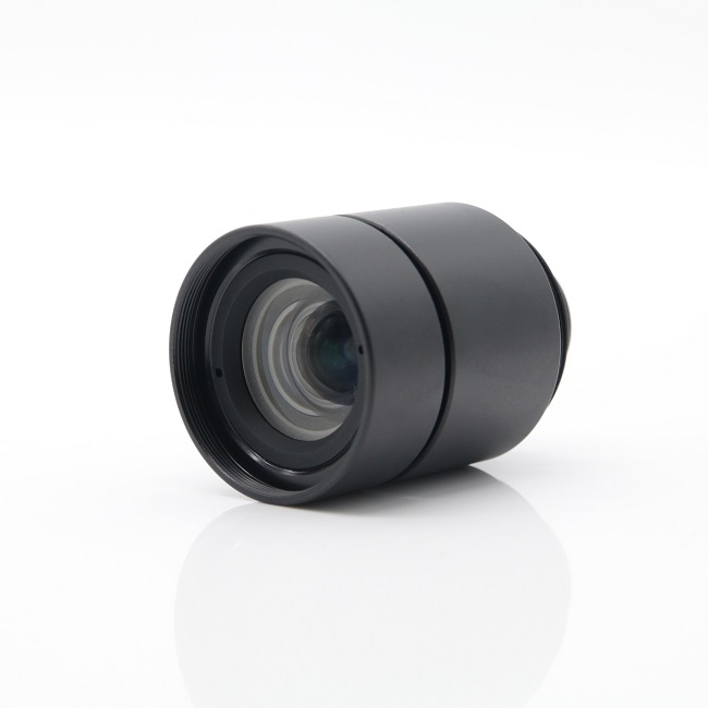
A Line Scan Inspection Lens excels in highly specific industrial scenarios. Let us examine four primary high-value applications.
Continuous web inspection remains the most common use case globally. Rolling processes manufacture endless miles of paper, textiles, foil, and glass. Battery films also move at extremely high speeds. A single continuous camera detects microscopic defects instantly. It captures a flawless image strip without any frame overlap. Finding a tiny pinhole in a battery separator film prevents catastrophic battery failures.
Cylindrical surface unrolling presents another major optical advantage. Inspecting curved surfaces usually creates frustrating optical distortion. Standard cameras struggle to keep the entire curve in focus simultaneously. By spinning bottles, cans, or mechanical shafts, a single row of pixels captures the surface incrementally. Software then flattens this cylindrical data into a perfect 2D image. You can read barcodes or inspect labels as if they were laid flat.
Many legacy production lines face severe space constraints. Standard area cameras are often bulky and heavy. Their matching optics demand wide physical clearance above the belt. Conversely, this specific architecture features a very narrow optical footprint. You can fit it into tight machine enclosures easily. It peers through narrow gaps in the machinery where area cameras simply cannot fit.
Finally, high-resolution sorting relies heavily on this linear architecture. Conveyor belts move incredibly fast during food sorting or PCB inspection. You need ultra-high resolution across a very wide field of view. These specific lenses deliver sharp contrast across the entire conveyor width. They map out defective rice grains or broken solder joints with pinpoint accuracy.
Selecting the right optics determines your entire inspection accuracy. You must evaluate four critical dimensions carefully.
Your lens's image circle must physically exceed the linear sensor length. Linear sensors are typically much longer than standard rectangular sensors. If the lens circle is too small, mechanical vignetting occurs. This creates heavy edge darkening in your acquired images. You will lose vital inspection data at the extreme edges of the conveyor belt. Always verify the maximum sensor format supported by the lens documentation.
You must tightly align the lens’s spatial resolution with the camera's pixel pitch. We use the MTF curve to measure this contrast capability scientifically. Following established EMVA 1288 standard guidelines helps ensure reliable evaluation results. A high MTF rating guarantees you can reliably detect the smallest acceptable defect. If the lens cannot resolve the detail, the high-resolution sensor captures nothing but blurred pixels.
Physical mounting space is rarely unlimited on a factory floor. You must calculate the exact optical magnification required for your setup. This calculation depends directly on your physically available working distance. A mismatched magnification forces painful and expensive machine redesigns later. Measure the distance from the sensor plane to the target object accurately.
Color continuous scanning applications face unique and difficult optical challenges. White light contains many different visible wavelengths. These wavelengths bend differently when passing through glass, causing color fringing. You will see false color halos at the edges of the inspection zone. You should evaluate specialized optics to prevent this issue. Apochromatic lenses correct color dispersion across the entire inspection spectrum perfectly.
Optical Parameter Evaluation Matrix
| Parameter | Risk if Ignored | Best Practice |
|---|---|---|
| Image Circle | Severe edge darkening (vignetting). | Ensure circle exceeds sensor length. |
| MTF / Resolving Power | Blurred details; missed microscopic defects. | Match spatial resolution to pixel pitch. |
| Working Distance | Inability to focus within machine limits. | Calculate exact magnification upfront. |
| Chromatic Control | False color artifacts and fringing. | Use apochromatic glass for color tasks. |
Deploying these systems exposes several hidden bottlenecks and integration risks. Experience shows excellent optics alone cannot guarantee success.
The most critical dependency is intense illumination. These systems require powerful, highly focused line lights. Because the object moves incredibly fast, exposure times are astonishingly short. Under-illuminating the subject renders the highest-quality lens completely useless. You will capture nothing but dark, noisy data. LED line lights combined with cylindrical focusing lenses usually provide the required intensity.
Next, you must address mechanical synchronization and distortion. A critical link exists between the camera frame rate and the conveyor encoder. The lens captures exactly what passes its narrow field of view. If the hardware encoder mismatches the camera line rate, the image suffers immediately. You get stretched or compressed images. This aspect ratio distortion ruins dimensional measurements entirely.
Vibration sensitivity is another major risk factor we see often. We emphasize the absolute need for highly rigid optical mounting. Micro-vibrations blur the single-pixel line instantly. Consider a pixel pitch of 5 microns. If the mounting bracket vibrates by just 10 microns, your image blurs across two entire pixels. This wipes out edge detection algorithms instantly. Secure the camera, lens, and lighting to a mechanically isolated frame.
Finally, understand the strict Depth of Field (DoF) limitations. You often need wide apertures to gather enough light rapidly. However, wide apertures inherently create a very shallow DoF. This physical trade-off requires strict material flatness during the inspection process. If the web material flutters up and down, it leaves the focal plane. Defect detection drops significantly when optical focus is lost. Watch out for uneven conveyor rollers or tensioning issues.
How do you confidently specify your optics? Follow a structured shortlisting logic to avoid common pitfalls. Begin by looking at the physical environment closely. Audit your space thoroughly before opening any manufacturer catalogs.
Magnification Calculation Chart
| Desired Magnification | Required Focal Length | Estimated Working Distance |
|---|---|---|
| 0.5x | 60mm | 180mm |
| 1.0x | 60mm | 120mm |
| 2.0x | 60mm | 90mm |
Note: Values are estimated examples. Always verify exact optical formulas with your lens manufacturer.
A specialized imaging setup solves complex, high-speed continuous inspection challenges gracefully. Standard cameras simply cannot process these demanding environments efficiently. By capturing data line by line, you eliminate motion blur and software stitching completely. You guarantee absolute precision across massive rolls of material.
Remember the interdependent optical triad. The lens, the camera sensor, and the lighting must be co-engineered. One poor component degrades the entire vision system instantly. You cannot fix bad lighting with a great lens.
Take action to secure your quality control today. Facility managers and vision engineers should schedule a technical consultation immediately. Request a lens evaluation unit to test against your materials. Test it directly against your specific defect-detection thresholds to ensure absolute reliability.
A: Line scan lenses are engineered to project a highly precise, long, and narrow optical image circle optimized for linear sensors, prioritizing edge-to-edge uniformity over a 2D grid.
A: While physically possible in some low-end applications, standard lenses often suffer from edge distortion, vignetting, and poor MTF when paired with large line scan sensors. Industrial-grade line scan lenses are recommended.
A: Tight spaces require shorter focal lengths or specialized optical path folding (via mirrors/prisms). The lens must achieve the required magnification within the exact working distance available on the machine frame.


