
Views: 0 Author: Site Editor Publish Time: 2026-08-02 Origin: Site


High-speed manufacturing faces a fundamental imaging bottleneck today. Traditional area scan cameras often struggle when capturing continuous webs, cylindrical objects, or massive flat surfaces. Motion blur, lighting inconsistencies, and image stitching errors frequently compromise defect detection rates. You need a better approach to handle these demanding geometries. An Industrial Line Scan Lens serves as the critical optical bridge required for 1D continuous image acquisition. It captures incredibly precise, narrow slices of an object to form a seamless image over time. This article provides an objective evaluation framework for your machine vision system. We will help you determine exactly when a line scan architecture becomes necessary. You will also learn how to specify the correct optical components to maximize production yield and eliminate inspection blind spots.
Area scan systems encounter severe physical limits when dealing with fast-moving targets. An area sensor captures a full 2D frame simultaneously. Moving objects cause pixel smearing during the sensor exposure time. You can shorten the exposure time to freeze motion. However, this demands exponentially more light. When inspecting massive components, a single area scan camera lacks sufficient resolution. Engineers often deploy multiple area cameras side-by-side to solve this. They rely on complex stitching software to merge the images. This approach introduces heavy processing overhead. Stitching errors frequently occur at the overlapping seams, causing false defect reports.
The line scan alternative completely changes this paradigm. A line scan camera utilizes a single row of pixels. It captures this narrow line at exceptionally high frequencies, often exceeding 100,000 lines per second. As the object moves under the camera, the system builds a seamless 2D image over time. It functions much like a desktop flatbed scanner. This method eliminates overlapping frames entirely.
Engineers often debate the initial engineering cost versus the resulting yield. Line scan setups require precise motion control and intense lighting. This makes initial integration more expensive than standard area scan systems. However, the return on investment becomes clear quickly. High-resolution line scanning ensures zero-defect continuous production runs. You avoid costly product recalls and minimize scrap material. The long-term yield improvements easily justify the initial optical and mechanical investments.
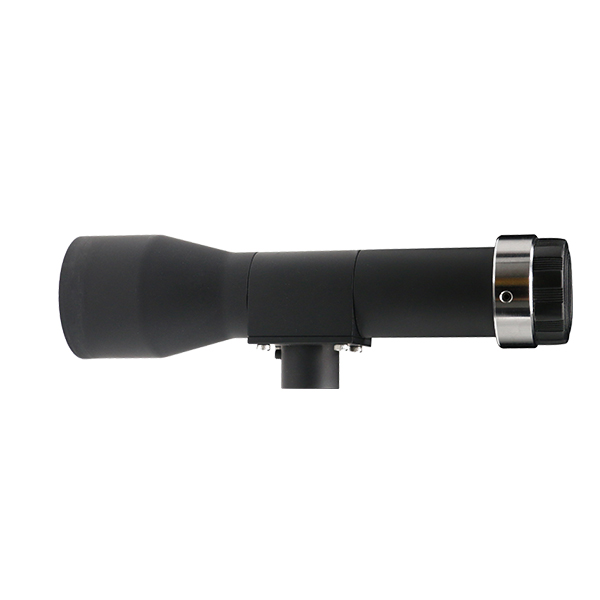
Line scan technology requires specialized optical engineering to function correctly. Standard photography lenses fail under these extreme industrial demands. Line scan sensors utilize massive physical dimensions. A 16K resolution line sensor can measure up to 82mm in length. Such vast dimensions require lenses engineered with exceptionally large image circles. If the image circle falls short of the sensor length, vignetting occurs. The image corners turn dark, and resolution drops off sharply at the edges. Industrial optics prevent this by utilizing large internal glass elements.
Maintaining uniformity across the entire field of view is critical. Standard lenses perform well in the center but lose sharpness near the perimeter. Industrial line scan lenses undergo rigorous optical engineering to prevent this degradation. They maintain consistent light transmission from the center to the extreme edges. Furthermore, they sustain a high Modulation Transfer Function (MTF) across the entire sensor surface. This ensures uniform contrast and sharpness regardless of where a defect appears.
Distortion control represents another vital mechanism. Optical distortion causes straight lines to appear curved. This destroys measurement accuracy in machine vision systems. Industrial lenses undergo specific optical corrections to guarantee sub-pixel accuracy. They utilize advanced lens element groupings to flatten the field. This precise distortion control is non-negotiable. It allows inspection algorithms to measure defect sizing down to the micron level reliably.
Table 1: Optical Performance Characteristics
| Feature | Standard Area Scan Lens | Industrial Line Scan Lens |
|---|---|---|
| Image Circle Size | Typically under 35mm | Up to 82mm or larger |
| Edge Resolution | Often degrades significantly | Maintained consistently (High MTF) |
| Distortion Control | Acceptable for general viewing | Corrected for sub-pixel accuracy |
| Target Geometry | Static or slow-moving frames | Continuous webs and cylinders |
Specifying the correct lens requires a strict formulaic approach. You cannot select optics based on field of view alone. You must match the physical pixel size and the total sensor length to the lens design. Common line scan pixels measure 3.5µm or 5µm. The optical magnification dictates how the physical object maps onto these microscopic pixels. First, determine your required optical magnification. Divide the sensor pixel size by your desired object resolution. Next, ensure the lens operates optimally at this specific magnification. Lenses are optimized for distinct magnification ranges. Using a lens outside its designed range introduces severe optical aberrations.
You must evaluate a lens's resolving power before purchase. MTF charts provide the most objective measurement of optical performance. They illustrate how well a lens transfers contrast from the object to the sensor. You need to verify the lens can resolve the required line pairs per millimeter (lp/mm). The formula is straightforward: 1000 divided by double the pixel size (in microns). For a 5µm pixel, you need a lens capable of resolving 100 lp/mm. Review the MTF chart carefully. Ensure the contrast remains above 20% at your target lp/mm across the entire image circle. Ignore lenses lacking published MTF data.
Color line scan applications demand additional optical scrutiny. Different wavelengths of light bend at different angles when passing through glass. This phenomenon causes chromatic aberration. You will see color fringing along the high-contrast edges of inspected materials. To prevent this, you must specify an apochromatic (APO) corrected lens. APO lenses utilize specialized low-dispersion glass. They focus red, green, and blue wavelengths onto the exact same focal plane. This correction is absolutely necessary for color sorting applications, printing inspection, and precise boundary measurements.
Flat panel display manufacturing requires flawless surface inspection. Producers must examine massive OLED and LCD glass substrates. They look for dead pixels, mura (clouding), and microscopic scratches. Area scan cameras cannot capture an entire television panel at high resolution. They also introduce spatial distortion at the screen corners. Only line scan optics offer the necessary field of view and resolution. A Display Panel Inspection Lens traverses the massive glass sheet flawlessly. It captures billion-pixel images without any spatial distortion. This guarantees uniform quality control across every square millimeter of the display panel.
Roll-to-roll manufacturing moves materials at blistering speeds. Paper, foil, textiles, and steel coils often travel at hundreds of meters per minute. Defect detection must occur in real-time. The success criteria involve identifying pinholes, coating inconsistencies, or surface scratches immediately. Area cameras suffer severe motion blur at these speeds. Line scan lenses thrive here. They capture single rows of pixels in microseconds. This effectively freezes the motion of the continuous web. By analyzing the continuous data stream, the vision system tracks defects instantly. It can then trigger automated cutting or marking systems further down the production line.
Inspecting round objects poses unique geometric challenges. Depth of field limits cause the edges of cylinders to fall out of focus in area scans. Perspective distortion alters the physical dimensions of features near the curve. Line scan lenses solve this by unwrapping cylindrical objects. The system rotates objects like batteries, automotive shafts, or print rollers. The line scan camera remains focused exclusively on the apex of the cylinder. As the object spins, the camera builds a flat 2D image. This transforms a complex 3D surface into a seamless flat plane. It allows standard pattern matching algorithms to inspect the entire 360-degree surface easily.
High-end optics cannot overcome poor mechanical integration. System builders often underestimate the surrounding infrastructure required for line scanning. To ensure success, you must address three critical deployment realities.
First, address the severe lighting intensity demands. Line scan cameras utilize incredibly short exposure times. Exposures often drop to fractions of a millisecond to freeze fast-moving objects. Standard factory lighting will leave the sensor entirely underexposed. You must deploy specific high-intensity line lights. LED line lights focused through cylindrical rod lenses provide intense, concentrated illumination. For extreme high-speed applications, laser line generators become mandatory. Proper lighting geometry—such as brightfield or darkfield—dictates the visibility of specific defect types.
Second, respect the mechanical alignment sensitivity. Line scan systems possess a very shallow depth of field. The camera, lens, and target object must remain perfectly perpendicular. A fraction of a degree in misalignment causes severe focus degradation. One end of the sensor line will appear sharp while the other blurs. You must utilize rigid, 6-axis adjustment mounts. Avoid flimsy brackets. Vibration from industrial machinery also ruins line scan images. Isolate the camera mounts from heavy floor vibrations whenever possible.
Third, overcome the synchronization hurdles. The camera capture rate must perfectly match the physical speed of the conveyor or roller. If the conveyor speeds up, the camera must capture lines faster. If synchronization fails, the resulting image stretches or compresses. This destroys all dimensional measurement accuracy. You must use hardware rotary encoders. Connect the encoder directly to the camera's trigger input. This perfectly syncs the line rate with physical motion. We strongly warn against relying on software-only timing workarounds. Software timers cannot account for microscopic physical speed variations.
Common Mistakes to Avoid:
Selecting the right components requires a logical sequence. Do not guess your hardware needs. Start by defining the smallest defect size you must detect. Once you know the defect size, select a sensor resolution capable of mapping that defect across at least three pixels. Next, specify the industrial line scan lens. Ensure its image circle covers the sensor and its MTF resolves your pixel pitch. Finally, engineer the lighting and rigid mechanical mounts to support the optics.
We advise buyers to demand hard data before procurement. Request specific lens testing data from the manufacturer. Ask for MTF reports and distortion charts matched exactly to your working distance and magnification requirements. Generic specifications often hide performance drops at the edges of the lens.
Always encourage proof-of-concept testing. Consult with optical engineers or experienced vision integrators. Borrow or rent the specified lens and camera. Test them on your actual production material moving at real-world speeds. Buying strictly off spec sheets frequently leads to costly integration failures. A physical test validates the entire optical, mechanical, and illumination chain.
A: You derive the focal length from three specific variables. You need the required Field of View (FOV) across the object, the physical working distance, and the physical length of the line sensor. By matching the magnification ratio between the sensor length and the FOV, you can calculate the optimal focal length. Lens manufacturers provide optical calculators to simplify this exact mathematical relationship.
A: You can only do this if the line sensor is shorter than the lens's image circle. This typically restricts you to smaller 2K or 4K sensors. For larger 8K or 16K sensors, standard F-mount lenses cause severe vignetting (dark corners). You require specialized M-mount or custom flange lenses to cover these massive sensors adequately.
A: Telecentric line scan lenses eliminate parallax error entirely. Standard lenses view objects at an angle near the edges, causing perspective distortion. Telecentric optics capture parallel light rays across the entire field. This makes them ideal for precise metrology. They accurately measure thick objects or parts featuring varying heights without dimensional distortion.


